Installation and setup guide for the HS-FLS100+ Z-Wave Floodlight Sensor
Overview
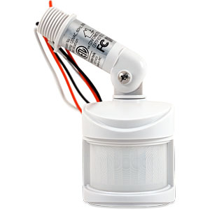
HS-FLS100-G2 is a PIR module that’s designed to retrofit onto existing outdoor floodlights. It features a PIR sensor to detect motion through movement of heat sources and a LUX sensor for determining brightness of its surroundings. It is equipped with Z-Wave Plus wireless communication capability that will convert an ordinary motion-activated floodlight into a smart home device.
Operating Modes
HS-FLS100+ is very versatile and may be used in a variety of ways.
-
Conventional Floodlight Mode HS-FLS100-G2 can be used as a conventional motion-activated floodlight sensor to power floodlights when motion is sensed during dark hours. Controls are provided for manual adjustment of LUX sensitivity and floodlight ON times.
-
Smart Floodlight Mode When added to a smart home system, HS-FLS100-G2 will send Z-Wave commands to the smart hub or home controller when motion is sensed and when the LUX level changes. Likewise, the smart hub or home controller can send Z-Wave commands back to the HS-FLS100-G2 to turn floodlights ON and OFF. This added functionality provides a very high level of flexibility not typically available in conventional motion-activated floodlights.
-
Smart Sensor Mode HS-FLS100-G2 can also be installed and used simply as an outdoor motion, LUX and temperature sensor. Floodlight functionality is not required. This brings some interesting security and smart home possibilities!
S2 Security
This product supports the S2 security protocol that uses encrypted Z-Wave Plus messages to communicate to other security-enabled Z-Wave Plus products. A security-enabled Z-Wave Plus controller must be used in order to fully utilize the security features of this product.
Physical Installation
Installation must be performed by skilled technicians who are informed about the standards and technical requirements of the appliance and its proper installation. Check your local codes as they apply to your situation. If the house wiring is of aluminum, consult with an electrician about proper wiring methods. Before proceeding with the installation,
TURN OFF THE POWER TO THE LIGHTING CIRCUIT AT THE CIRCUIT BREAKER OR FUSE BOX TO AVOID ELECTRICAL SHOCK.
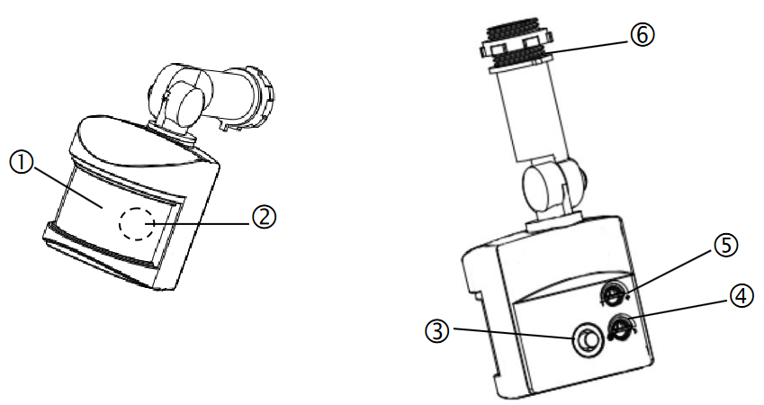
Features and Controls
|
|
1 - PIR Lens |
|
2 - LED indicator (hidden behind lens) |
|
|
3 - Link button |
|
|
4 - Lux knob |
|
|
5 - Timer Knob |
|
|
6 - Threaded arm |
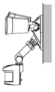
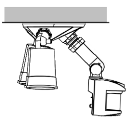
Below diagram show a typical assembly of HS-FLS100-G2 on a floodlight fixture (not provided).
|
Wall Mount |
Under Eave Mount |
|---|---|
|
|
|
Safety Precautions
-
DO NOT install when it is raining.
-
Isolate the power supply before installation.
-
Ensure that local Wiring and Building regulations are complied with.
-
The unit is supplied with a pre-wired supply cable this must be used and must
-
not be removed.
-
Total lighting load to HS-FLS100-G2 not exceed:
-
300W incandescent @ AC120V
-
100W LED @ AC120V with 0.8 pF Driver
-
Installation & Wiring Instructions
Note: As with any outdoor installation work it is always recommended to start early during the day.
WARNING: TURN OFF POWER BY REMOVING POWER FUSE OR TURNING OFF CIRCUIT BREAKER BEFORE INSTALLATION.
Taking down the existing floodlight
-
With mains supply turned off, if possible, remove the lamps from the bulb holders of the existing floodlight to avoid any damage during the installation.
-
Carefully detach the floodlight from the wall by removing its mounting screws. Keep all parts for reuse later, including any rubber rings. Take note the direction of the rubber gasket as it needs to be reassembled later in the same way.
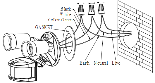
-
Disconnect the mains wire from the floodlight by untwisting the wire nuts.
-
When done, place the floodlight on a table to prepare for wiring the HS-FLS100-G2.
Removing old motion sensor
(Skip this section if the existing floodlight has no motion sensor)
-
Locate the wires coming from the old motion sensor, usually colored black, white and red.
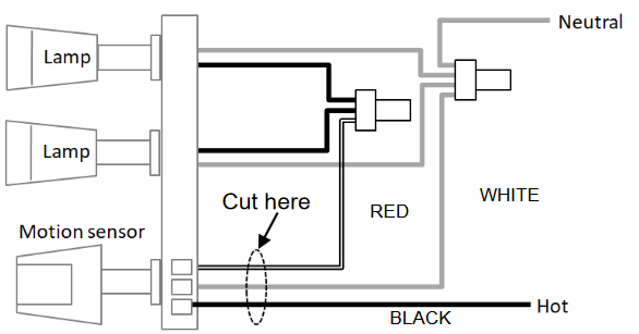
-
Disconnect the wires of the motion sensor by cutting it if necessary.
-
Remove the old motion sensor from the mounting base by twisting its threaded arm counter clockwise.
Wiring the FLS100
-
Screw the threaded arm of HS-FLS100-G2 into the mounting base. For typical wall installation, HS-FLS100-G2 should be located at the bottom of the mounting base.
-
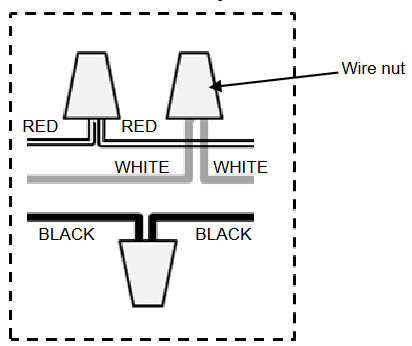
Connect up the wiring as in the diagram below, using wire nuts to join the wires. If replacing an old motion sensor, simply follow the same wiring color as the old motion sensor.
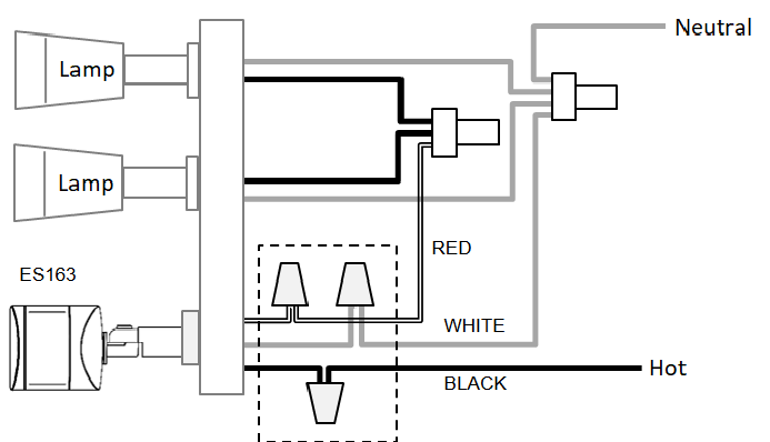
-
Route the power leads Hot and Neutral through the rubber gasket to get ready for wall mount. Ensure the rubber gasket is facing the same direction as it was before.
-
When completed, turn the knob of Time-Off on the unit to “T” mark, and turn the knob of Lux on the unit to the “ ” mark.

Assembling back the floodlight
-
Connect back the mains wire as before. Tuck the wire nuts and excess cable neatly inside the junction box.
-
Screw the lighting floodlight back into position using its mounting screws. Place the rubber rings back into their positions.
-
Insert the lamps removed earlier back into the bulb holders, adjust the lamp direction if necessary.
-
Reinstate the power supply to the floodlight and switch on the wall switch, if installed. The floodlight will turn on for around 60 seconds for warm up and then turn off. It is now in ‘Test Mode’.
Walk Test
The user can perform a walk test to ensure the PIR detector’s range falls within the desired area of coverage.
-
Walk through its PIR Detector coverage area. The floodlight turns on when you move and turns off after approximately 5 seconds. Wait for the floodlight to turn off before the next test.
-
When you are satisfied with the coverage area you can now set the desired Time period and Lux level.
The sensitivity of the PIR can be adjusted after the Inclusion to a Z-wave controller, using Parameter 8 configuration (refer to Z-wave configuration settings in the Programming section).
Time and Lux adjustment
You can set desired Time period and Lux level via either of these options;
-
Use your Z-Wave controller (hub) to send Time period and Lux settings to your FLS100 (see next section)
-
Manually adjust the knobs on the back of FLS100 in the following manner:
-
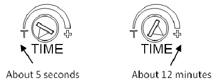
Time adjustment
Time-off knob controls how long the floodlight will stay on after the motion is detected. Turning the knob towards the + mark increases the time (up to about 12 minutes) or towards the T mark decreases it (down to about 8 seconds). The recommended setting is around midpoint of the scale giving approximately 5 minutes.
-
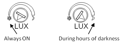
Lux adjustment
The LUX knob sets the threshold of ambient brightness level that will activate the motion sensor. The knob can be adjusted between “ ” mark (always trigger regardless of light level) and the moon symbol (trigger only when dark). The adjustable Lux range is about 10 - 900 Lux.
-
To set the lux level, turn the Time-off knob to “T” for maximum response.
-
Turn the LUX control knob to the “moon” (dusk) position.
-
Wait until the ambient light reaches the level of darkness at which you wish the floodlight to activate.
-
Slowly rotate the Lux knob anti-clockwise while keep creating motion during the process until the floodlight turns on. At this position the light will operate at approximately the same level of darkness each evening.
-
Set the Time-off knob back to the desired preset time.
When connected to a Z-wave controller, this manual setting will be overwritten by the settings through the Z-wave controller.
-
-
Z-Wave Setup
Inclusion
FLS100 must be included into your Z-Wave network to be controlled by your hub. Follow these instructions to perform inclusion. Note: HS-FLS100-G2 also supports Z-wave SmartStart technology which allows inclusion of device with controller through automatic means, or through a quick scan of a QR code. The controller must support Z-wave SmartStart feature for it to work.
-
Make sure the FLS100 is powered
-
Place your Z-Wave controller or hub into inclusion mode
-
Quickly press the FLS100 link button 3 times (within 1.5 seconds). The LED behind the PIR lens will blink rapidly during inclusion and will stop blinking when inclusion is complete.
If inclusion is unsuccessful, exclude or factory reset FLS100 and try inclusion again.
Exclusion
FLS100 may be excluded from your Z-Wave network using the following procedure.
-
Make sure the FLS100 is powered
-
Place your Z-Wave controller or hub into exclusion mode
-
Quickly press the FLS100 link button 3 times (within 1.5 seconds). Check your controller app to confirm when exclusion is complete.
Factory Reset
This procedure may be used to reset your device if a Z-Wave controller is not available.
-
Make sure the FLS100 is powered
-
Quickly press the FLS100 link button 3 times (within 1.5 seconds).
-
Within 1 second of step 1, press the link button again and hold it until the LED turns off (approx 5 seconds).
-
Node ID is excluded. The device reverts to factory default state.
Z-Wave Association Information
HS-FLS100+ supports the following Z-Wave association groups.
-
Group 1: Association with 1 Controller Node (Lifeline)
-
Group 2: Association with 4 nodes (i.e. end devices such as smart plugs and other lighting controllers). This allows the PIR detector on the unit to transfer commands directly to other Z-wave end devices without the participation of the controller. This has the effect that when its detector triggers, all devices associated with unit will be operated.
Z-Wave Parameters
Use the parameters below to adjust HS-FLS100 configuration settings
|
Parameter |
Description |
Bytes |
Value |
Default |
|---|---|---|---|---|
|
1 |
ON Time
|
2 |
8-720 (seconds) |
180 |
|
2 |
Lux Sensor Threshold
|
2 |
10-900 |
50 |
|
3 |
Sensor Report Interval
|
2 |
1-1440 (minutes) |
10 |
|
4 |
Notification Report on Motion |
1 |
0 : Disable alert
|
1 |
|
5 |
Load Control Mode |
1 |
0 : Load controlled by Z-Wave Only
|
1 |
|
6 |
Load Control Sensor Mode |
1 |
0 : Load controlled by Lux and Motion
|
0 |
|
7 |
Temperature Offset
|
1 |
0x9C - 0x64
|
0x00 |
|
8 |
Motion Sensitivity |
1 |
0: low level, approx. 6m distance
|
0 |
Specifications
|
PIR Tilting Angle |
140° |
|---|---|
|
Mounting Height |
Recommended 2.0 ~ 3.0m height on normal brick wall |
|
PIR Detection |
Max. distance 20m, max. angle of 120°
|
|
PIR Swivel Angle |
Up to 90° Leftward, Up to 90° Rightward |
|
PIR warm-up time |
Approx. 60 seconds |
|
Lux Adjustment |
Approximately 10 ~ 900 Lux |
|
Timer Adjustment |
Approximately 8 seconds ~ 12 minutes |
|
Working Temperature |
-4°F - +104°F |
|
Dimension (H x W x D) |
60mm x 55mm x 60mm |
|
Protection Degree |
IP44 – Weather proof |
|
Certifications |
Z-Wave Plus, FCC, ETL |
Troubleshooting
|
Symptom |
Possible Cause |
Recommendation |
|---|---|---|
|
Floodlight does not turn on for 5
|
Power is not
|
|
|
Cannot carry out inclusion and
|
Floodlight already
|
Perform a factory reset. |
|
Floodlight flashes on and off |
The unit’s lux sensor
|
Change the angle and direction of
|
|
Z-wave controller cannot
|
Out of range. |
|
|
Floodlight remains on |
PIR detector triggered by
|
|
Supported Z-Wave Command Classes
-
COMMAND_CLASS_ZWAVEPLUS_INFO_V2
-
COMMAND_CLASS_ASSOCIATION_V2
-
COMMAND_CLASS_ASSOCIATION_GRP_INFO_V1
-
COMMAND_CLASS_TRANSPORT_SERVICE_V2
-
COMMAND_CLASS_VERSION_V3
-
COMMAND_CLASS_MANUFACTURER_SPECIFIC_V2
-
COMMAND_CLASS_DEVICE_RESET_LOCALLY_V1
-
COMMAND_CLASS_POWERLEVEL_V1
-
COMMAND_CLASS_SECURITY_2
-
COMMAND_CLASS_SUPERVISION_V1
-
COMMAND_CLASS_FIRMWARE_UPDATE_MD_V4
-
COMMAND_CLASS_NOTIFICATION_V8
-
COMMAND_CLASS_SWITCH_BINARY_V1
-
COMMAND_CLASS_SENSOR_MULTILEVEL_V5
-
COMMAND_CLASS_CONFIGURATION_V1
-
COMMAND_CLASS_SENSOR_BINARY_V1
-
COMMAND_CLASS_MULTI_CHANNEL_ASSOCIATION_V3
FCC Statement
This equipment has been tested and found to comply with the limits for a Class B digital device, pursuant to Part 15 of the FCC Rules. These limits are designed to provide reasonable protection against harmful interference in a residential installation. This equipment generates, uses and can radiate radio frequency energy and, if not installed and used in accordance with the instructions, may cause harmful interference to radio communications. However, there is no guarantee that interference will not occur in a particular installation. If this equipment does cause harmful interference to radio or television reception, which can be determined by turning the equipment off and on, the user is encouraged to try to correct the interference by one of the following measures:
-
Reorient or relocate the receiving antenna.
-
Increase the separation between the equipment and receiver.
-
Connect the equipment into an outlet on a circuit different from that to which the receiver is connected.
-
Consult the dealer or an experienced radio/TV technician for help.
Un-license band: This device complies with Part 15 of the FCC Rules. Operation is subject to the following two conditions: (1) This device may not cause harmful interference, and (2) this device must accept any interference received, including interference that may cause undesired operation.
FCC Caution: Any changes or modifications not expressly approved by the party responsible for compliance could void the user's authority to operate this equipment.
This transmitter must not be co-located or operating in conjunction with any other antenna or transmitter.
-
To comply with FCC RF exposure compliance requirements, a separation distance of at least 20 cm must be maintained between the antenna of this device and all persons.
-
This Transmitter must not be co-located or operating in conjunction with any other antenna or transmitter