Online manual for the HS-WX300 R1 (700 Series) In-wall Dimmer & Switch
Overview
HS-WX300 is a Z-Wave® in-wall light switch that may be configured to operate as either a dimmer switch or an on/off switch. It may be installed with or without a neutral wire and it works with both wired and wireless companion switches in 3-way circuit configurations. This switch has been designed, tested and certified for use in the United States and Canada.
WARNING RISK OF FIRE | RISK OF ELECTRICAL SHOCK | RISK OF BURNS - DO NOT USE THIS SWITCH TO CONTROL ANYTHING THAT MAY PRESENT A HAZARD WHEN CONTROLLED REMOTELY OR USED IN AN UNATTENDED FASHION. DO NOT USE WITH MEDICAL AND LIFE SUPPORT INSTRUMENTS.
CAUTION:
-
To Reduce the Risk of Overheating And Possible Damage To Other Equipment, Do Not Install To Control A Receptacle, A Motor-Operated Appliance, A Fluorescent Lighting Fixture, Or A Transformer-Supplied Appliance.
-
If used with non-dimming loads, be sure to configure as a an on-off switch before powering the load.
Circuit Types
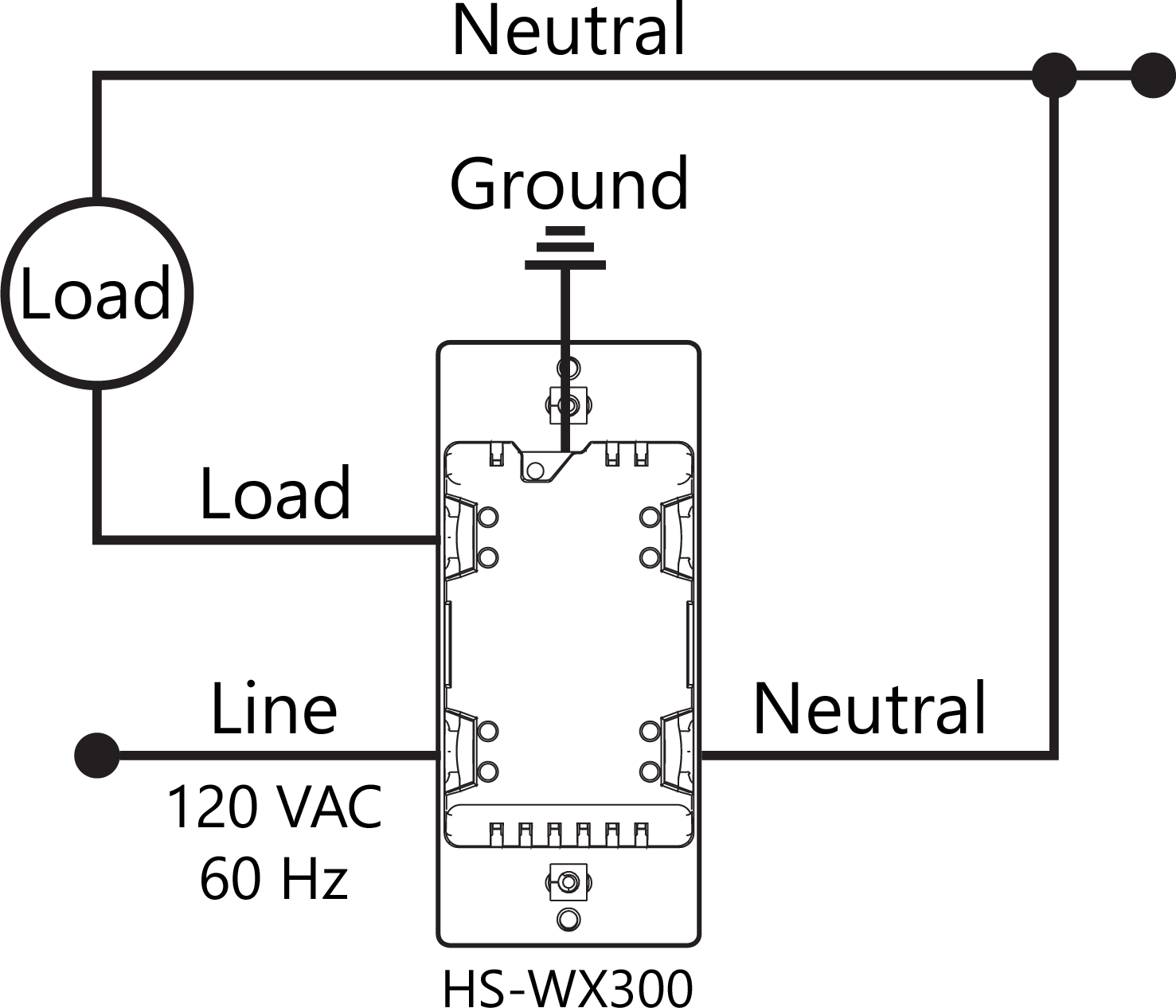
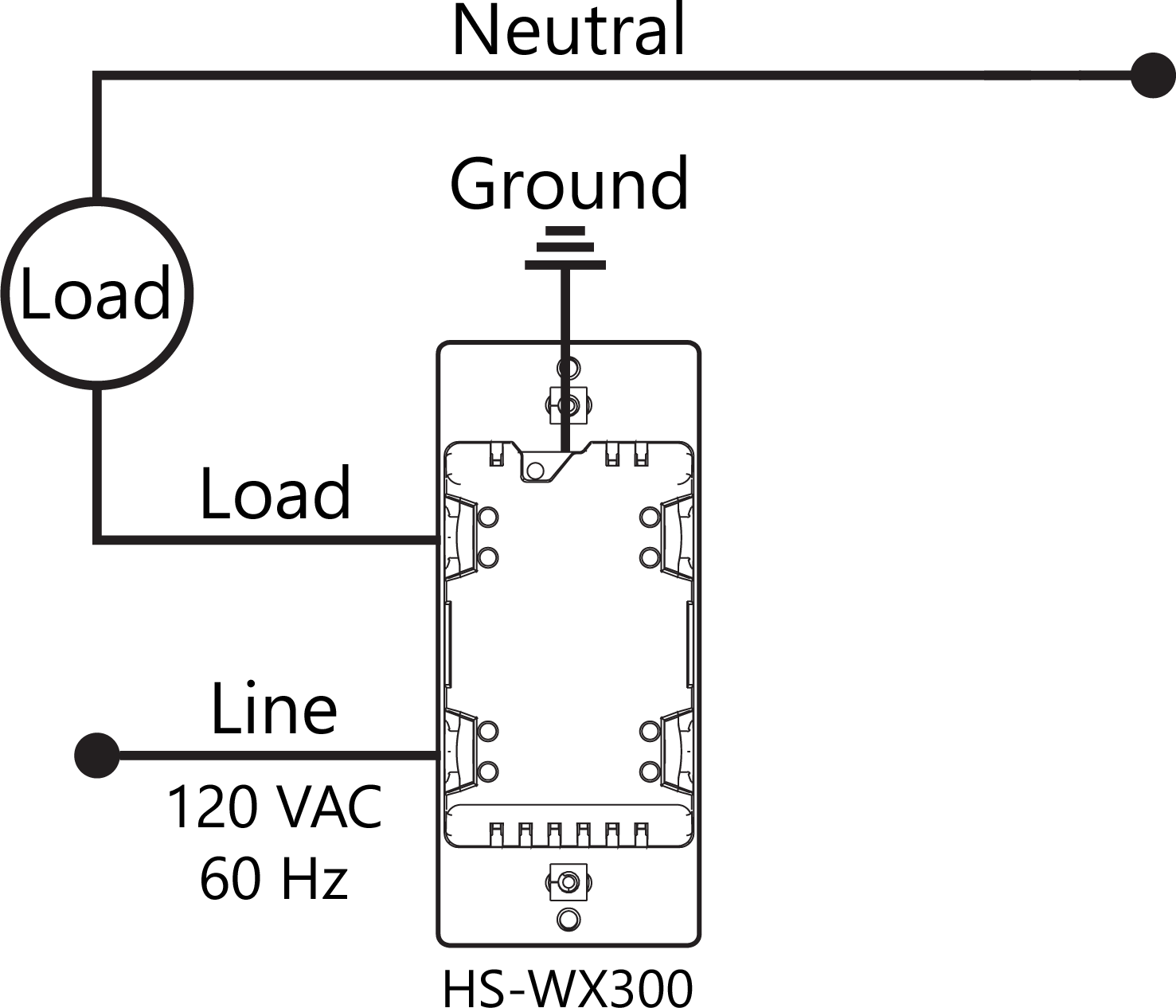
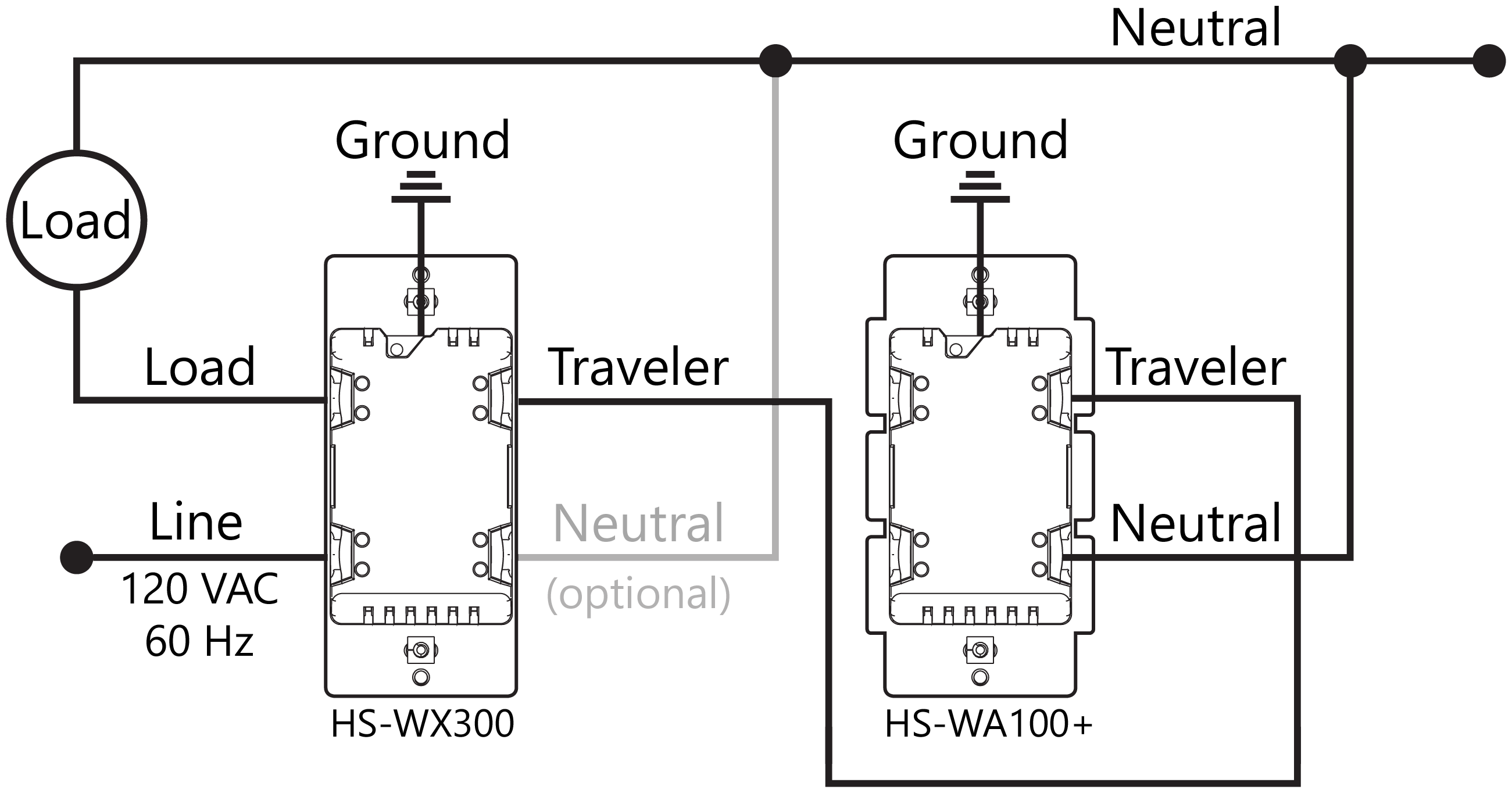
Most lighting loads are powered with line (120 VAC) and neutral wires. The line wire always runs through the wall switch box but the neutral may not be present there. If the neutral wire is present, use the 3-wire method below. If no neutral is present, use the 2-wire method. For 3-way circuits, a neutral is only required at the companion switch location (using HS-WA100+ or standard 3-way switches).
|
Single Switch, 3-Wire Circuit |
Single Switch, 2-Wire Circuit |
|---|---|
|
|
|
|
Multi Switch (3-Way) Wiring for 2-Wire & 3-Wire Circuits |
|---|
|
|
|
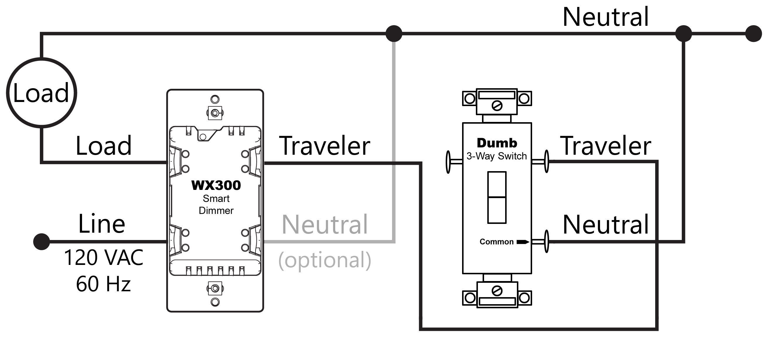
Multi Switch (3-Way) Wiring with “Dumb” 3-Way Companion Switch |
|---|
|
This configuration works with a standard (“dumb”) on/off (non-dimming, non-lighted) 3-way switch. Note that the dimming and multi-tap features of the WX300 will not be controllable from the dumb switch. |
|
|
Installation
Tools required
-
Medium Standard (flat head) Screwdriver
-
Medium Philips Screwdriver
-
Wire Cutter & Stripper
Steps
-
Shut off power to the circuit at the circuit breaker or fuse box.
VERIFY power is OFF before continuing!
-
Remove existing switch’s wall plate and mounting screws. Carefully remove the existing switch from the electrical box but leave the wires connected.
-
There may be up to five wires connected to the existing switch. Make note of these wires and label, if necessary, to ensure correct installation of the HS-WX300. You will need to match these wires with the corresponding screw terminals on the HS-WX300.
LINE, and LOAD wires are required for every installation. If a NEUTRAL wire is present, we recommend using that also for best performance, particularly for dimming loads. Wires are usually color-coded for easy identification. However, colors can deviate from what’s shown in the list below, depending upon the original installer. We recommend using a multi-meter or voltage detector to verify which wire is actually connected to power before wiring. In general, the colors follow the convention below.
-
-
LINE (120 VAC) - Black (connected to power)
-
NEUTRAL - White (this wire is often tied to other neutral wires and may require a jumper to connect with the HS-WX300)
-
LOAD - Black (connected to load)
-
GROUND — Green or Bare
-
TRAVELER — Red/Other (only used in 3-way circuits)
-
-
-
Disconnect the wires from the existing switch and attach those wires to the HS-WX300 using the screw terminal connectors on the back with the following procedure:
-
Strip 16 mm (5/8”) insulation from each wire*.
-
With a screw driver, loosen each screw terminal by rotating the screw counter-clockwise a few turns until resistance is felt.
-
There are two holes on the back of the switch near each screw terminal. Insert the stripped wire into one of these holes and tighten the screw terminal to secure the connection. Connections should be snug. *all wires should be 14 AWG or larger rated at 80°C or higher. Tightening torque should be 12 lbf-in (14kgf-cm). Use copper wire only.
-
Carefully install the wired switch back into the electrical box and reattach the trim plate.
Configuration
WX300 works with HS3 and HS4 system using these plugins:
-
HS3: Z-Wave Core version 3.0.9.0 (or later)
-
HS4: Z-Wave version 4.0.1.0 (or later)
Changing Switch Mode
(Must be done BEFORE Z-Wave inclusion)
HS-WX300 may be configured to operate as an ON-OFF switch or as a DIMMER. By default, it will operate as a dimmer. If you're installing it to control a non-dimming load or wish to only provide ON-OFF operation, be sure to configure it to operate as an ON-OFF switch. To change the switch mode, follow these steps:
-
Press & hold the small button located on the metal yoke next to the column of LEDs, OR if the trim plate is already installed, in rapid succession, tap the top paddle 3 times, then press & hold the top paddle for 3 seconds (tap-tap-tap-press & hold)
-
Observe the behavior of the LEDsIf all LEDs blink green 3 times, HS-WX300 is configured to function as a dimmerIf the bottom LED blinks blue 3 times, HS-WX300 is configured to function as an on-off switch
Changing Wire Mode
HS-WX300 may be installed with a neutral wire (3-wire mode) or without a neutral wire (2-wire mode). Selecting the correct wire mode will yield the best results, especially if the switch is configured as a dimmer. By default, 3-wire mode is enabled. To change the wire mode (at the switch):
-
Turn the power off
-
In rapid succession, tap the top paddle 2 times, then press & hold the top paddle for 3 seconds (tap-tap-press & hold)
-
Observe the behavior of the LEDsIf the bottom 3 LEDs flash white 3 times, HS-WX300 is configured for 3-wire modeIf the bottom 2 LEDs flash white 2 times, HS-WX300 is configured for 2-wire mode
Note: Wire mode may also be changed by the hub using Z-Wave parameter 32. See the Z-Wave Parameters section at the end of this user guide.
Z-Wave Inclusion or Exclusion
Follow this 2-step procedure to add (or remove) your new HomeSeer switch to (or from) your Z-Wave network:
-
Put your Z-Wave controller into inclusion (or exclusion) mode. Consult your controller’s manual if you’re unsure how to do this.
-
In rapid succession, tap the bottom paddle 2 times, then press & hold the bottom paddle for 3 seconds (tap-tap-press & hold). This will initiate the inclusion (or exclusion) process. Note: The switch will default to dimmer mode after Z-Wave exclusion.
Factory Reset
To be used only in the event that the network primary controller is lost or otherwise inoperable.
-
In rapid succession, tap the top paddle 3 times, then tap the bottom paddle 3 times. If all LEDs flash white 5 times, factory reset was successful. If not, repeat this procedure.
Note: As this must be done very quickly, we recommend using 2 fingers for this operation; one on each paddle!
Note: The switch will default to 3-wire mode and dimmer mode after factory reset.
Association
This product supports Group 1 and Group 2 Associations with up to five Z-Wave devices per group. Group 1 supports Lifeline Communication, Group 2 supports Basic Set, refer to your controller manual for instructions on setting up these features.
Operation
Your new HomeSeer switch may be operated locally (by pressing the paddle) or remotely using a Z-Wave compatible hub or system
Local Control
-
Press (tap) the top of the paddle to power the load.
-
Press (tap) the bottom of the paddle to cut power to the load.
-
If configured as a dimmer, press and hold the top or bottom of the paddle increase or decrease the dim level.
Remote Control
On / Off / Dim control is available remotely using wireless Z-Wave commands. Consult your controller manual for details.
HomeSeer Compatibility
Your new HomeSeer switch is Z-Wave certified and is ready to be used with a wide variety of home automation hubs and controllers. All features are fully supported by HomeSeer systems but some Advanced Features (see below) may not be fully supported by other controllers. If you’re using another brand of controller, be sure to check with that company to determine compatibility.
Advanced Features
Your new HomeSeer switch includes advanced features that may be accessed with HomeSeer and other systems.
Multi-tap scene control or event triggering
Tapping the top or bottom of the paddle 1, 2, 3, 4 or 5 times in rapid succession will broadcast Z-Wave central scene commands to the hub. These commands may be used to trigger automations (like HomeSeer events).
RGB LED Indicators
The color of all LED indicators may be controlled with Z-Wave parameter commands from the hub. This may be done manually or via automations, if supported by the hub. HomeSeer hubs are designed to send these parameter commands with event actions.
-
Normal mode: LED indicators glow to reflect the on/off/dim status of the connected load using a palette of 7 possible colors (red, green, blue, cyan, magenta, yellow, white).
-
Status mode: Individual LEDs can be controlled to reflect the status of nearly anything in the home. For example, one LED can be programmed to glow yellow when the garage door is open. Another LED can blink red when motion is sensed in the driveway. The possibilities are endless.
-
Switching between normal mode and status mode: HS-WX300 switches operate in normal mode by default unless or until a status command is received. When that happens, normal mode is suspended and the switch goes into status mode. It will stay in status mode until all status LEDs are turned off. At that point, the switch will revert to normal mode.
Note: If a switch is operating in status mode, manually dimming it will cause the LEDs to operate temporarily in normal mode. After the dimming operation is complete, the switch will revert to status mode.
Toggle Mode
When Toggle Mode is enabled, WX300 functions like a single push-button switch. The load will be toggled on and off, regardless of which part of the paddle you press. This is especially useful for switches that are installed into dark locations or where users may have accessibility issues. This feature is set using Z-Wave parameter commands (see table below for details).
Smart Bulb Mode
This feature is designed to disable load control when the paddle is pressed. Instead, power is always supplied to the load, and paddle presses are only used to send Z-Wave commands to the controller. This feature is especially useful for circuits that are powering smart bulbs. This feature is set using Z-Wave parameter commands (see table below for details) or you can set this using a paddle tap sequence (3x UP, then 1x DOWN).
Default Dim Level
This feature applies to WX300s that are configured to operate as dimmers. By default, WX300 is designed to turn on to the previous dim level when powered on from an off state. This feature allows you to override that behavior and turn on to an absolute dim level instead. This feature is set using Z-Wave parameter commands (see table below for details).
Non-HomeSeer Compatibility
The special features of this switch are supported using a number of different Z-Wave technologies. HomeSeer systems are designed to support these technologies and will provide the most seamless operation of these features. However, other systems may also provide satisfactory results depending on the level of support they provide for these same technologies. If you’re using a non-HomeSeer system, use the information below and consult with your system manufacturer to determine the level of compatibility.
Multi-tap scene control or event triggering
This feature uses the Z-Wave CENTRAL SCENE command class. If the system supports this command class AND utilizes a general interrogation process for inclusion, this feature should work. However, if the system employs an inclusion process based on the Z-Wave product ID, then specific product support would need to be implemented.
RGB LED Indicators
This feature is supported using Z-Wave parameter commands. Most Z-Wave certified systems provide a method for issuing parameter commands to individual products. HomeSeer systems simplify the use of this feature by providing event actions to send parameter commands. A complete list of parameters may be found on the next page.
Instant Status
This feature is supported using a Z-Wave SWITCH MULTILEVEL REPORT (dimmer mode) and SWITCH BINARY REPORT (on-off switch mode) and the CENTRAL SCENE command class. All Z-Wave certified systems should support the SWITCH MULTILEVEL REPORT feature.
Attention SmartThings users
A special Edge Driver is required to enable your hub to use the advanced features of this switch. Use this procedure to install the driver:
Procedure
-
If you have HomeSeer devices already installed on your hub, remove them first.
-
Navigate to the HomeSeer Edge Driver Channel and log in with your Samsung SmartThings account.
-
Click Enroll
-
Click Available Drivers
-
Click Install. It may take a few minutes for the driver to be installed onto your SmartThings hub
-
To add a HomeSeer device, scan for nearby devices or enter the setup code found on the device.
Z-Wave SmartStart
SmartStart enabled products can be added into a Z-Wave network by scanning the Z-Wave QR Code* with a controller providing SmartStart inclusion. No further action is required and the SmartStart product will be added automatically within 10 minutes of being switched on in the network vicinity.
*QR Code is located on the HS-WX300 metal yoke under the switch paddle.
Interoperability
This product can be operated in any Z-Wave network with other Z-Wave certified devices from other manufacturers. All mains operated nodes within the network will act as repeaters regardless of vendor to increase reliability of the network
Z-Wave Parameters
Use the parameters below to adjust HS-WX300 configuration settings
|
Parameter |
Description |
Bytes |
Value |
Default |
Dimmer Mode |
Switch Mode |
Firmware |
|---|---|---|---|---|---|---|---|
|
3 |
Sets bottom LED operation (in normal mode) |
1 |
0 = Bottom LED ON if load is OFF
|
1 |
Y |
Y |
v1.12 |
|
4 |
Sets paddle’s load orientation |
1 |
0 = Top of Paddle turns load ON
|
0 |
Y |
Y |
v1.12 |
|
5 |
Sets the lowest dimming threshold |
1 |
Possible values: 1-14
|
1 |
Y |
N |
v1.12 |
|
6 |
Enables/Disables Central Scene and multiple tap functions |
1 |
0 = Central Scene Enabled, controls load with delay. Enables Multi-tap and press and hold
|
0 |
Y |
Y |
v1.12 |
|
11 |
Set dimmer Ramp rate for remote control |
1 |
Possible values: 0-90
|
3 |
Y |
N |
v1.12 |
|
12 |
Set dimmer Ramp rate for local control |
1 |
Possible values: 0-90
|
3 |
Y |
N |
v1.12 |
|
13 |
Sets the display mode of the LEDs |
1 |
0=Normal mode (LEDs show load status)
|
0 |
Y |
Y |
v1.12 |
|
14 |
Sets the Normal display mode LED color |
1 |
Possible values: 0-6
|
0 |
Y |
Y |
v1.12 |
|
21 |
Sets the Status mode LED 1 (bottom) color |
1 |
Possible values: 0-7
|
|
Y |
Y |
v1.12
|
|
22 |
Sets the Status mode LED 2 color |
1 |
|||||
|
23 |
Sets the Status mode LED 3 color |
1 |
|||||
|
24 |
Sets the Status mode LED 4 color |
1 |
|||||
|
25 |
Sets the Status mode LED 5 color |
1 |
|||||
|
26 |
Sets the Status mode LED 6 color |
1 |
|||||
|
27 |
Sets the Status mode LED 7 (top) color |
1 |
|||||
|
30 |
Sets the dimmer Blink frequency for All LEDs in Status mode |
1 |
Possible values: 0, 1-255
|
5 |
Y |
Y |
v1.12 |
|
31 |
Sets LED(s) 1-7 to Blink in Status mode |
1 |
Bitmask defines specific LEDs to enable for blinking: Note: this decimal value is derived from a hex code calculation based on the following: Bit 0 = led 1, Bit 1 = led 2, Bit 2 = led 3, Bit 3 = led 4, Bit 4 = led 5, Bit 5 = led 6, Bit 6 = led 7 IE: value of 1 = first LED, 64 = led 7 |
0 |
Y |
Y |
v1.12 |
|
32 |
Sets the Wire mode / no neutral mod of the switch |
1 |
0 = 3 wire mode (Neutral, Line, & Load)
|
0 |
Y |
Y |
v1.12 |
|
33 |
Sets Startup Flash Behavior |
1 |
0 = LEDs do not flash on startup 1 = LEDs flash on startup to indicate switch or dimmer operation |
1 |
Y |
Y |
v1.13 |
|
34 |
Sets relative LED indicator brightness |
1 |
Possible values: 0-6 0=Lowest intensity
|
3 |
Y |
Y |
v1.13 |
|
35 |
Sets Paddle Behavior for Switch Mode (Toggle Feature) |
1 |
0 = Top paddle press turns load ON. Bottom paddle press turns load OFF. 1 - Either paddle press turns load ON if OFF and OFF if ON. |
0 |
N |
Y |
v1.13 |
|
36 |
Sets Default Dim Value when turned ON via paddle press |
1 |
Possible values: 0-99 0 = LAST dim level when switch was last turned off
|
0 |
Y |
N |
v1.13 |
|
37 |
Sets Load Control via Paddle (Smart Bulb Feature) |
1 |
0 = Load is controlled with paddle 1 = Load is not controlled with paddle |
0 |
Y |
Y |
v1.13 |
Specifications
|
Power |
Requirements |
120VAC / 60 Hz |
|---|---|---|
|
Max Load |
Incandescent | Dimmable CFL/LED |
600 watts | 300 watts |
|
Min Load |
All types |
24 watts (0.2A) |
|
Incandescent De-rating |
Double-gang Box |
500 watts |
|
|
Triple-gang Box |
400 watts |
|
Temperatures |
Operating | Storage |
0℃ → 40℃ | -20℃ → 60℃ |
|
Z-Wave |
Frequency |
908.4/916 MHz (US/CAN) |
|
|
Range |
100+ ft. (line of sight) |
|
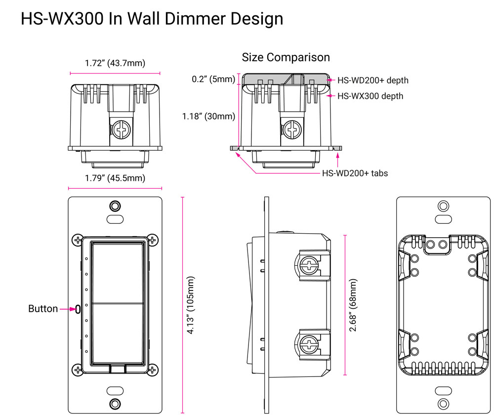
Dimensions |
Metal Yoke |
1.79" x 4.13" (45.5mm x 105mm) (W x H) |
|
|
Plastic Housing |
1.72" x 2.68" x 1.18" (43.7mm x 68mm x 30mm) (W x H x D) |
|
Certifications |
UL (US, Canada), FCC/IC, Z-Wave Plus® |
|
|
UL Specifications |
For indoor use only | Operating ambient temperature 0-40°C | Method of mounting included: Independently mounted (Vertical position only) | Operating control, Type 1.B action | Pollution Degree 2 | Rated Impulse Voltage 2500 V | Software Class A |
|
Supported Z-Wave Command Classes
This device supports the Indicator Command Class, version 3 and supports the Indicator ID 0x50 (Identify) and Properties ID 0x03, 0x04 and 0x05.
|
|
SWITCH_MULTILEVEL (Dimmer Mode) |
SWITCH_BINARY
|
||
|
Command Class |
Version |
Security |
Version |
Security |
|---|---|---|---|---|
|
COMMAND_CLASS_ZWAVEPLUS_INFO |
V2 |
|
V2 |
|
|
COMMAND_CLASS_ASSOCIATION |
V2 |
S2 |
V2 |
S2 |
|
COMMAND_CLASS_ASSOCIATION_GRP_INFO |
V3 |
S2 |
V3 |
S2 |
|
COMMAND_CLASS_DEVICE_RESET_LOCALLY |
V1 |
S2 |
V1 |
S2 |
|
COMMAND_CLASS_FIRMWARE_UPDATE_MD |
V5 |
S2 |
V5 |
S2 |
|
COMMAND_CLASS_INDICATOR |
V3 |
S2 |
V3 |
S2 |
|
COMMAND_CLASS_MANUFACTURER_SPECIFIC |
V2 |
S2 |
V2 |
S2 |
|
COMMAND_CLASS_MULTI_CHANNEL_ASSOCIATION |
V3 |
S2 |
V3 |
S2 |
|
COMMAND_CLASS_POWERLEVEL |
V1 |
S2 |
V1 |
S2 |
|
COMMAND_CLASS_SECURITY_2 |
V1 |
|
V1 |
|
|
COMMAND_CLASS_SUPERVISION |
V1 |
S2 |
V1 |
S2 |
|
COMMAND_CLASS_TRANSPORT_SERVICE |
V2 |
|
V2 |
|
|
COMMAND_CLASS_VERSION |
V3 |
S2 |
V3 |
S2 |
|
COMMAND_CLASS_SWITCH_MULTILEVEL |
V4 |
S2 |
N/A |
N/A |
|
COMMAND_CLASS_SWITCH_BINARY |
N/A |
N/A |
V2 |
S2 |
|
COMMAND_CLASS_CONFIGURATION |
V4 |
S2 |
V4 |
S2 |
|
COMMAND_CLASS_CENTRAL_SCENE |
V3 |
S2 |
V3 |
S2 |
|
COMMAND_CLASS_BASIC |
V2 |
S2 |
V2 |
S2 |
Physical Dimensions
Warranty
HomeSeer warrants to the original purchaser that this product, for the warranty period, will be free from material defects and workmanship. This warranty is subject to proper installation and operation of the product. HomeSeer’s sole obligation, under this warranty, is to repair, replace or correct any defect that was present at the time of delivery. This warranty does not extend to consequential or incidental damage to other products that may be used with this product. Warranty claims must be submitted in writing directly to HomeSeer at HomeSeer.com. Warranty period: limited 2 years from date of purchase
FCC statements:
This device complies with part 15 of the FCC Rules. Operation is subject to the following two conditions: (1) This device may not cause harmful interference, and (2) this device must accept any interference received, including interference that may cause undesired operation.
NOTE: The Caution: The user is cautioned that changes or modifications not expressly approved by the party responsible for compliance could void the user's authority to operate the equipment.
Note: This equipment has been tested and found to comply with the limits for a Class B digital device, pursuant to part 15 of the FCC Rules. These limits are designed to provide reasonable protection against harmful interference in a residential installation. This equipment generates, uses and can radiate radio frequency energy and, if not installed and used in accordance with the instructions, may cause harmful interference to radio communications. However, there is no guarantee that interference will not occur in a particular installation. If this equipment does cause harmful interference to radio or television reception, which can be determined by turning the equipment off and on, the user is encouraged to try to correct the interference by one or more of the following measures:
—Reorient or relocate the receiving antenna.
—Increase the separation between the equipment and receiver.
—Connect the equipment into an outlet on a circuit different from that to which the receiver is connected.
—Consult the dealer or an experienced radio/TV technician for help.
This equipment complies with FCC radiation exposure limits set forth for an uncontrolled environment. This equipment should be installed and operated with a minimum distance of 20cm between
the radiator and any part of your body."
IC statements
This device contains licence-exempt transmitter(s)/receiver(s) that comply with Innovation, Science and Economic Development Canada’s licence-exempt RSS(s). Operation is subject to the following two conditions:
(1) This device may not cause interference.
(2) This device must accept any interference, including interference that may cause undesired operation of the device.
L’émetteur/récepteur exempt de licence contenu dans le présent appareil est conforme aux CNR d’Innovation, Sciences et Développement économique Canada applicables aux appareils radio exempts de licence. L’exploitation est autorisée aux deux conditions suivantes :
(1) L’appareil ne doit pas produire de brouillage;
(2) L’appareil doit accepter tout brouillage radioélectrique subi, même si le brouillage est susceptible d’en compromettre le fonctionnement.
This equipment complies with ISED RSS-102 radiation exposure limits set forth for an uncontrolled environment. This equipment should be installed and operated with a minimum distance of 20cm between the radiator and any part of your body.
Pour se conformer aux exigences de conformité CNR 102 RF exposition, une distance de séparation d'au moins 20 cm doit être maintenue entre l'antenne de cet appareil ettoutes les personnes."
Supplier’s Declaration of Conformity
47 CFR 2.1077 Compliance Information
Responsible Party – US Contact Information
10 Commerce Park North, Unit 10
Bedford, NH 03110 United States
Model: WD700
https://homeseer.com/support-home
This product employs or practices certain features and/or methods of the following U.S. Patents: U.S. Patent Nos.6,891,838, 6,914,893 and 7,103,511.