WS300 User Guide
Online manual for the WS300 (800 Series) In-wall smart switch
This online manual supersedes the printed manual included with the WS300 as shipped
Overview
WS300 is a Z-Wave in-wall light switch that operates as an on/off switch. It must be installed with a neutral wire and it works with conventional 3-way switches in 3-way circuit configurations. This switch has been designed, tested and certified for use in the United States and Canada.
WARNING RISK OF FIRE | RISK OF ELECTRICAL SHOCK | RISK OF BURNS - DO NOT USE THIS SWITCH TO CONTROL ANYTHING THAT MAY PRESENT A HAZARD WHEN CONTROLLED REMOTELY OR USED IN AN UNATTENDED FASHION. DO NOT USE WITH MEDICAL AND LIFE SUPPORT INSTRUMENTS.
CAUTION:
To Reduce the Risk of Overheating And Possible Damage To Other Equipment, Do Not Use with Loads that Exceed the Maximum Loads Specified Below.
Circuit Types
WS300 may be used with single pole (1-switch) circuits and 3-way (2-switch) circuits.
Single Pole Circuit
A single pole circuit is designed to control a light or device from one location. This is the most common circuit type in most homes. The wiring diagram below illustrations how to install the WS300 in this type of circuit.
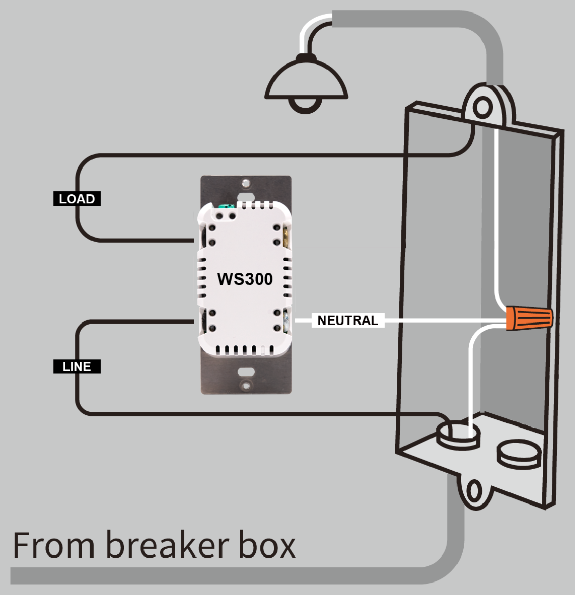
If present, the ground wire (not pictured) should be connected to the green terminal on the top of the WS300.
3-Way Circuit
A 3-way circuit is designed to control a light or device from two separate locations. This is useful in areas like staircases, hallways, or large rooms where it’s convenient to operate the light from either end. While there are many ways to wire a 3-way circuit, the illustrations below show two common wiring configurations. In figure b, the load wires are present in the same (local) electrical box as the WS300. In figure c, the load wires are present in the other (remote) electrical box with the standard 3-way switch. Note that any standard wall switch may be used as an accessory switch. It’s also possible to use companion switches by HomeSeer (WA100) and Jasco by setting Z-Wave parameter 40 to 1 (pulse mode). Also, if you do not have a traveler wire or wish to support multi-taps on the accessory switch, you can install another WS300 at that location as long as neutral wire is available.
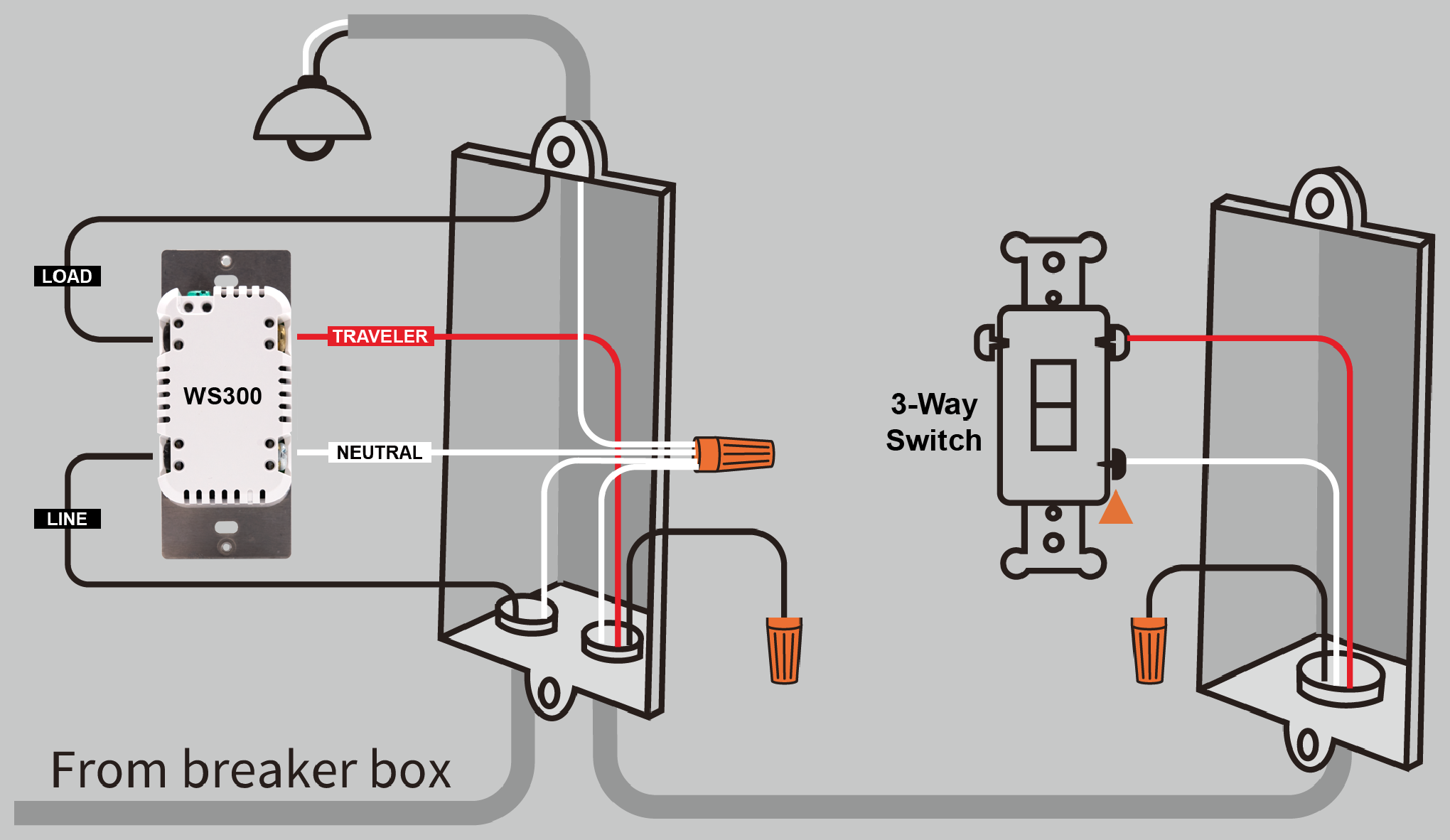 (b) 3-Way Circuit (Local Load) | 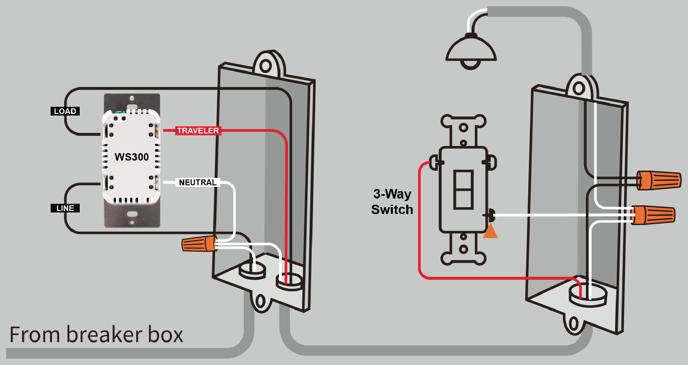 (c) 3-Way Circuit (Remote Load) |
If present, the ground wire (not pictured) should be connected to the green terminal on the top of the WS300.
CAUTION: If your wiring differs from these configurations, you may need to use a multi-meter to identify the wires and determine the correct wiring configuration. Always consult with a licensed electrician if you’re not sure how to proceed!
Installation
Tools required
Medium Standard (flat head) Screwdriver
Medium Philips Screwdriver
Wire Cutter & Stripper
Steps
Shut off power to the circuit at the circuit breaker or fuse box.
VERIFY power is OFF before continuing!
Remove existing switch’s wall plate and mounting screws. Carefully remove the existing switch from the electrical box but leave the wires connected.
There may be up to five wires connected to the existing switch. Make note of these wires and label, if necessary, to ensure correct installation of the WS300. You will need to match these wires with the corresponding screw terminals on the WS300.
LINE, LOAD and NEUTRAL wires are required for every installation. Wires are usually color-coded fore easy identification. However, colors can deviate from what’s shown in the list below, depending upon the original installer. We recommend using a multi-meter to verify which wire is actually connected to power before wiring. In general, the colors follow the convention below.
LINE (120 VAC) - Black (connected to power)
NEUTRAL - White (this wire is often tied to other neutral wires and may require a jumper to connect with the WS300)
LOAD - Black (connected to load)
GROUND — Green or Bare
TRAVELER — Red/Other (only used in 3-way circuits)
Disconnect the wires from the existing switch and attach those wires to the WS300 using the screw terminal connectors on the back with the following procedure:
Strip 16 mm (5/8”) insulation from each wire*.
With a screw driver, loosen each screw terminal by rotating the screw counter-clockwise a few turns until resistance is felt.
There are two holes on the back of the switch near each screw terminal. Insert the stripped wire into one of these holes and tighten the screw terminal to secure the connection. Connections should be snug. *all wires should be 14 AWG or larger rated at 80°C or higher. Tightening torque should be 12 lbf-in (14kgf-cm). Use copper wire only.
Carefully install the wired switch back into the electrical box and reattach the trim plate.
Configuration
Z-Wave Inclusion or Exclusion
Follow this 2-step procedure to add (or remove) your new HomeSeer switch to (or from) your Z-Wave network:
Put your Z-Wave controller into inclusion (or exclusion) mode. Consult your controller’s manual if you’re unsure how to do this.
In rapid succession, tap the paddle 2 Taps DOWN, 1 Hold DOWN (↓↓▼) to initiate the inclusion (or exclusion) process.
Note: The switch LED will blink magenta when in inclusion or exclusion mode.
Factory Reset
To be used only in the event that the network primary controller is lost or otherwise inoperable.
In rapid succession, tap the paddle 3 Taps UP, 3 Taps DOWN (↑↑↑↓↓↓). If the LED blinks 3 times, factory reset was successful. If not, repeat this procedure.
Note: Because this must be done very quickly, we recommend using 2 fingers for this operation; one on each paddle!
Association
This product supports Group 1 and Group 2 Associations with up to five Z-Wave devices per group.
Group 1: Supports Lifeline Communication,
Group 2: Supports Basic Set, refer to your controller manual for instructions on setting up these features.
Consult your smart home system manual for instructions on setting associations for the WS300.
Operation
Your new HomeSeer switch may be operated locally (by pressing the paddle) or remotely using a Z-Wave compatible hub or system
Local Control
Press (tap) the top of the paddle to power the load.
Press (tap) the bottom of the paddle to cut power to the load.
Remote Control
On / Off control is available remotely using wireless Z-Wave commands. Consult your controller manual for details.
Features & Compatibility
Your new HomeSeer switch is Z-Wave certified and is ready to be used with a wide variety of home automation hubs and controllers. All features are fully supported by HomeSeer systems but some features may not be fully supported by other controllers. If you’re using another brand of controller, be sure to check with that company to determine compatibility.
Multi-tap scene control or event triggering
Tapping the top or bottom of the paddle 1, 2, 3, 4 or 5 times in rapid succession will broadcast Z-Wave central scene commands to the hub. These commands may be used to trigger automations (like HomeSeer events).
This feature uses the Z-Wave CENTRAL SCENE command class. If the system supports this command class, this feature should work. However, if the system employs an inclusion process based on the Z-Wave product ID, then specific product support for the WS300 may need to be implemented.
RGB LED Indicator
The color of the LED indicator may be controlled with paddle tap sequences and with Z-Wave parameter commands sent from the hub. This may be done manually or via automations, if supported by the hub. HomeSeer hubs are designed to send these parameter commands with event actions.
Most Z-Wave certified systems provide a method for issuing parameter commands to individual products. HomeSeer systems simplify the use of this feature by providing event actions to send parameter commands. A complete list of parameters may be found below.
Normal mode: LED indicator glows to reflect the on/off status of the connected load using a palette of 10 standard colors (white, red, green, blue, magenta, yellow, cyan, pink, orange, teal) and 1 custom color (defined by user). Use the following methods to change the normal color:
Tap Sequence: In rapid succession, tap the paddle 2 Taps UP, 1 Tap DOWN (↑↑↓) to cycle through the colors in this order: white-red-green-blue-magenta-yellow-cyan-pink-orange-teal-custom. After custom, the colors will repeat.
Z-Wave Parameters: See parameter 14 in the table below for color values.
Custom: To set the LED to a custom color, you can change the RED, GREEN and BLUE values of the LED individually. Follow either of these procedures to create the custom color of your choice:
Procedure 1: Z-Wave Parameters: Use this procedure to achieve a greater level of precision and repeatability than what is possible with tap sequences. Refer to the standard color table below for help in creating a custom colors.
Use your hub to set Z-Wave parameter 14 to a value of 10. This will set the switch to the custom color. Note that the custom color will appear pink.
Changing RED: Set Z-Wave parameter 41 to the value of your choice from 0-100.
Changing GREEN: Set Z-Wave parameter 42 to the value of your choice from 0-100.
Changing BLUE: Set Z-Wave parameter 43 to the value of your choice from 0-100.
Procedure 2: Tap Sequence:
In rapid succession, tap the paddle 2 Taps UP, 1 Tap DOWN (↑↑↓) to advance to the next standard color. Repeat this process through all the 10 colors until your reach Custom. The sequence will be this: White, Red, Green, Blue, Magenta, Yellow, Cyan, Pink, Orange, Teal, Custom. Note that the default custom color will appear pink.
Changing RED:
To raise the RED level: 2 Taps UP, 1 Hold UP (↑↑▲)
To lower the RED level: 2 Taps UP, 1 Hold DOWN (↑↑▼)
Changing GREEN:
To raise the GREEN level: 3 Taps UP, 1 Hold UP (↑↑↑▲)
To lower the GREEN level: 3 Taps UP, 1 Hold DOWN (↑↑↑▼)
Changing BLUE:
To raise the BLUE level: 4 Taps UP, 1 Hold UP (↑↑↑↑▲)
To lower the BLUE level: 4 Taps UP, 1 Hold DOWN (↑↑↑↑▼)
Status mode: LED can be controlled to reflect the status of nearly anything in the home. For example, the LED can be programmed to glow red when the garage door is open and green when it is closed.
Switching between normal mode and status mode: WS300 switches operate in normal mode by default unless or until a status command is received. When that happens, normal mode is suspended and the switch goes into status mode. It will stay in status mode until the LED status is turned off. At that point, the switch will revert to normal mode.
Toggle Mode
When Toggle Mode is enabled, WS300 functions like a single push-button switch. The load will be toggled on and off, regardless of which part of the paddle you press. This is especially useful for switches that are installed into dark locations or where users may have accessibility issues. This feature is set using Z-Wave parameter commands (see table below for details).
Smart Bulb Mode
This feature is designed to disable load control when the paddle is pressed. Instead, power is always supplied to the load, and paddle presses are only used to send Z-Wave commands to the controller. This feature is especially useful for circuits that are powering smart bulbs.
To enable/disable this feature, use either of these methods:
Tap the paddle 3 Taps UP, 1 Tap DOWN (↑↑↑↓) to toggle smart bulb mode.
Adjust Z-Wave parameter 37 using the values in the Z-Wave Parameters table below.
Instant Status
This feature is supported using a Z-Wave SWITCH BINARY REPORT and the CENTRAL SCENE command class. All Z-Wave certified systems should support the SWITCH BINARY REPORT feature.
If your smart bulb is powered by this switch, be sure to turn the switch on (by pressing to the top of the paddle) before enabling the smart bulb feature.
Z-Wave SmartStart
SmartStart enabled products can be added into a Z-Wave network by scanning the Z-Wave QR Code* with a controller providing SmartStart inclusion. No further action is required and the SmartStart product will be added automatically within 10 minutes of being switched on in the network vicinity.
*QR Code is located on the WS300 metal yoke under the switch paddle.
Interoperability
This product can be operated in any Z-Wave network with other Z-Wave certified devices from other manufacturers. All mains operated nodes within the network will act as repeaters regardless of vendor to increase reliability of the network
Z-Wave Parameters
Use the parameters below to adjust WS300 configuration settings
Parameter | Description | Bytes | Value | Default |
|---|---|---|---|---|
3 | Sets LED operation (in normal mode) | 1 | 0 = LED OFF if load is OFF | 1 |
4 | Sets paddle’s load orientation | 1 | 0 = Top of Paddle turns load ON | 0 |
6 | Enables/Disables Central Scene and multiple tap functions | 1 | 0 = Central Scene Enabled, controls load with delay. Enables Multi-tap and press and hold | 0 |
13 | Sets the display mode of the LED | 1 | 0=Normal mode (LED shows load status) | 0 |
14 | Sets the Normal display mode LED color | 1 | Possible values: 0-10 | 0 |
21 | Sets the Status mode LED color | 1 | Possible values: 0-11 | 0 |
30 | Sets the Blink frequency for LED in Status mode | 1 | Possible values: 0, 1-255 | 5 |
31 | Sets LED to Blink in Status mode | 1 | 0=LED does not blink in status mode | 0 |
34 | Sets LED Brightness Level | 1 | Possible values: 0-6 | 5 |
35 | Sets Paddle Behavior for Switch Mode (Toggle Feature) | 1 | 0 = Top paddle press turns load ON. Bottom paddle press turns load OFF. 1 - Either paddle press turns load ON if OFF and OFF if ON. | 0 |
37 | Sets Load Control via Paddle (Smart Bulb Feature) | 1 | 0 = Load is controlled with paddle 1 = Load is not controlled with paddle | 0 |
38 | Sets Power Fail Recovery Behavior | 1 | 0 = Load is OFF | 2 |
40 | Sets Companion Switch Mode | 1 | 0 = Toggle Mode | 0 |
41 | Sets RED Brightness Level of the LED | 1 | Possible values: 0-100 | 5 |
42 | Sets GREEN Brightness Level of the LED | 1 | Possible values: 0-100 | 5 |
43 | Sets BLUE Brightness Level of the LED | 1 | Possible values: 0-100 | 5 |
Standard Color Table (RGB Values)
Color | Red | Green | Blue |
|---|---|---|---|
White | 10 | 100 | 100 |
Red | 50 | 0 | 0 |
Green | 0 | 100 | 0 |
Blue | 0 | 0 | 100 |
Magenta | 20 | 0 | 100 |
Yellow | 10 | 100 | 0 |
Cyan | 0 | 100 | 100 |
Pink | 25 | 20 | 25 |
Orange | 5 | 10 | 0 |
Teal | 0 | 100 | 10 |
Specifications
Power | Requirements | 120VAC / 60 Hz |
|---|---|---|
Max Load | Resistive | 15A (1875W) |
Incandescent | 1250W | |
Motor | 1/2 HP | |
Temperatures | Operating | Storage | 0℃ → 40℃ | -20℃ → 60℃ |
Z-Wave | Frequency | 908.4/916 MHz (US/CAN) |
Range | 100+ ft. (line of sight) | |
Dimensions | Switch body (inside electrical box) | 2.75 x 1.69 x 1.19” (HxWxD) |
Certifications | Z-Wave Plus LR, ETL |
Warranty
HomeSeer warrants to the original purchaser that this product, for the warranty period, will be free from material defects and workmanship. This warranty is subject to proper installation and operation of the product. HomeSeer’s sole obligation, under this warranty, is to repair, replace or correct any defect that was present at the time of delivery. This warranty does not extend to consequential or incidental damage to other products that may be used with this product. Warranty claims must be submitted in writing directly to HomeSeer at HomeSeer.com. Warranty period: limited 2 years from date of purchase.