

Setup guide for the HS ESPHome software plugin
Overview
The plugin is designed to allow HomeSeer HS4 to monitor and control ESPHome devices. ESPHome is an open-source system that lets you create custom firmware for ESP32 and ESP8266 boards without writing any code, using simple YAML configuration files.
Compatible Devices
Any device running an ESPHome firmware is compatible. You can flash ESPHome firmwares to compatible available devices, or create your own from scratch using supported microcontrollers (ESP32, ESP8266, BK72xx, RP2040 and others).
Requirements
HomeSeer Hub or HS4 Software
Setup
Go to Plugins > HS ESPHome > Manage Devices and click “Add ESPHome Device”. Enter:
-
the IP Address of your ESPHome device
-
the native API port , default is 6053
-
the encryption key as it appears in the api section of your YAML config file, or leave it blank if it does not use encryption
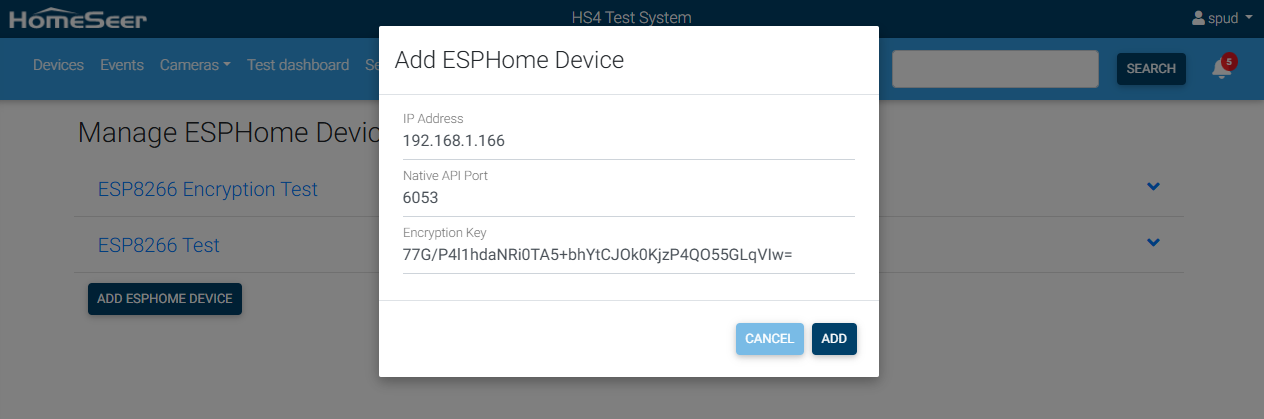
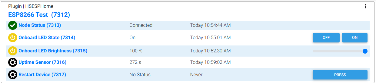
Click Add, the plugin will try to connect to the device, and if successfull it will create a HS Device corresponding to the components of your ESPHome device. Here is the device created for the example .yaml file that you can find below.
Creating your own ESPHome device
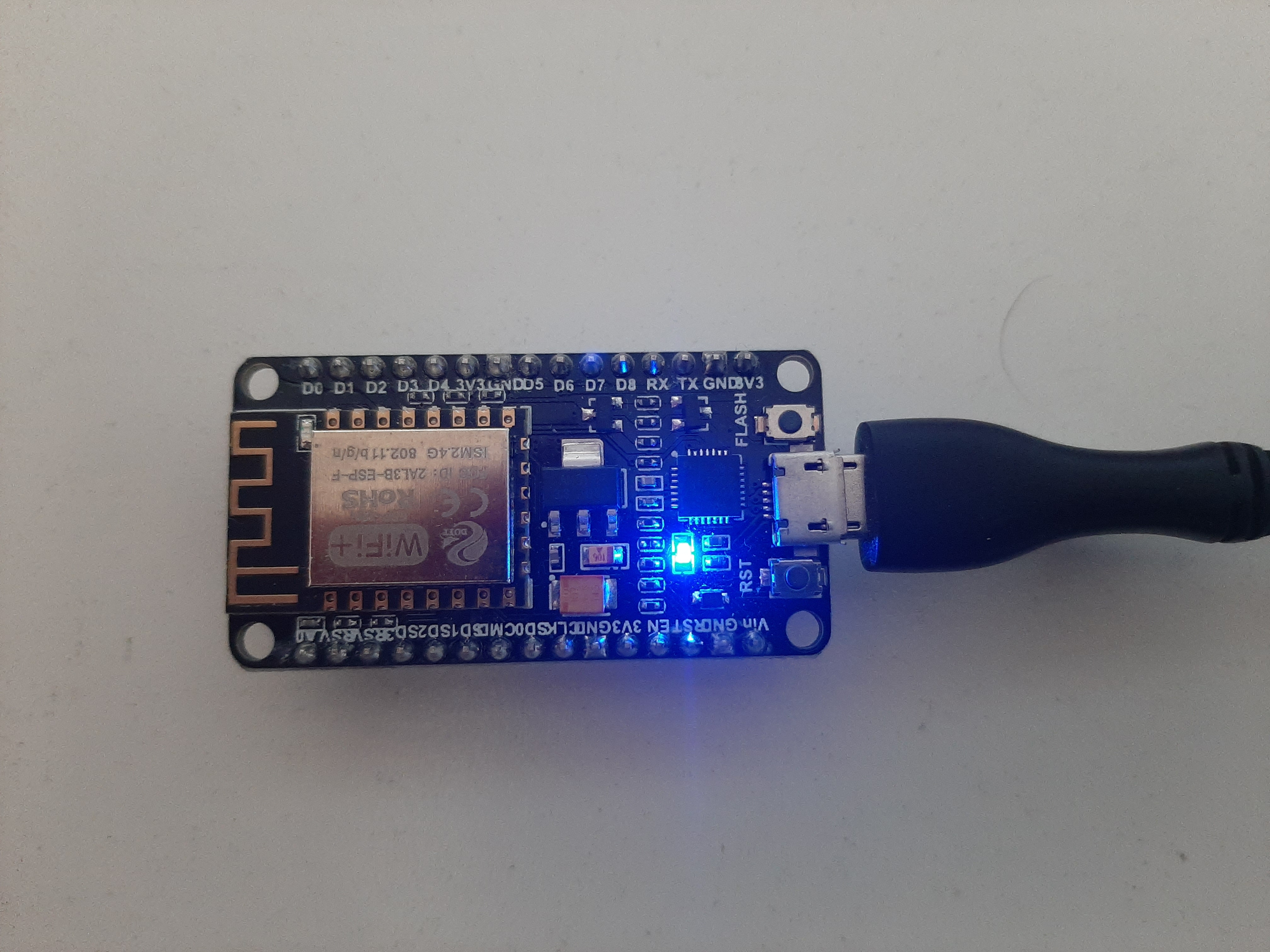
This example shows how to create and flash ESPHome firmware on a device. We will create a simple firmware for the ESP8266 NodeMCU microcontroller that lets you turn the onboard LED on or off, restart the device, and monitor an uptime sensor.
-
First you need to install ESPHome on a Windows, Linux or Mac computer using this guide.
-
To get a nice web interface you also need to install and start the ESPHome Device Builder (a.k.a dashboard)
# Install dashboard dependencies pip install tornado esptool # Start the dashboard esphome dashboard config -
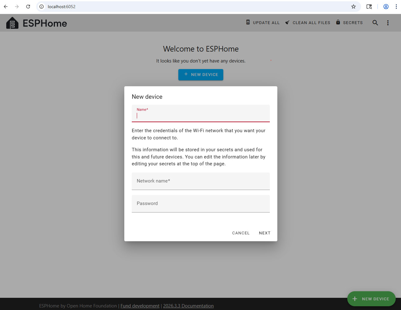
Go to http://localhost:6052 to open the dashboard. Click “New Device” then select “New Device Setup.”
-
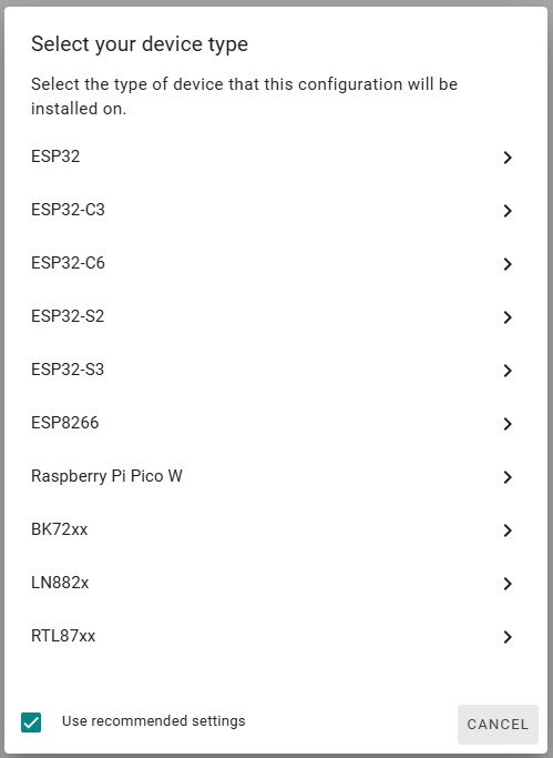
Enter a name for your device and your WiFi credentials. When prompted to connect to your device, click “Skip This Step.” Then select your device type; here, we use ESP8266.
-
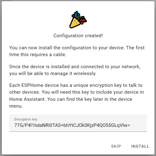
Click “Skip” again when prompted to install the configuration on your device.
-
Edit the configuration you just created to fit your needs. In our example, we added the web_server component, an uptime sensor, a restart button, and a light component that controls the NodeMCU's onboard LED:
esphome: name: esp8266-test friendly_name: ESP8266 Test esp8266: board: nodemcuv2 # Enable logging logger: # Enable API api: encryption: key: "77G/P4l1hdaNRi0TA5+bhYtCJOk0KjzP4QO55GLqVIw=" # Enable web server web_server: port: 80 sensor: - platform: uptime type: seconds update_interval: 30s name: Uptime Sensor output: - platform: esp8266_pwm id: onboard_led pin: number: D0 inverted: true light: - platform: monochromatic name: "Onboard LED" output: onboard_led id: led button: - platform: restart name: "Restart Device" ota: - platform: esphome password: "4908cb1286ce87467502f6c08562dd52" wifi: ssid: !secret wifi_ssid password: !secret wifi_password # Enable fallback hotspot (captive portal) in case wifi connection fails ap: ssid: "Esp8266-Test Fallback Hotspot" password: "JibrAvDfFU9R" captive_portal: -
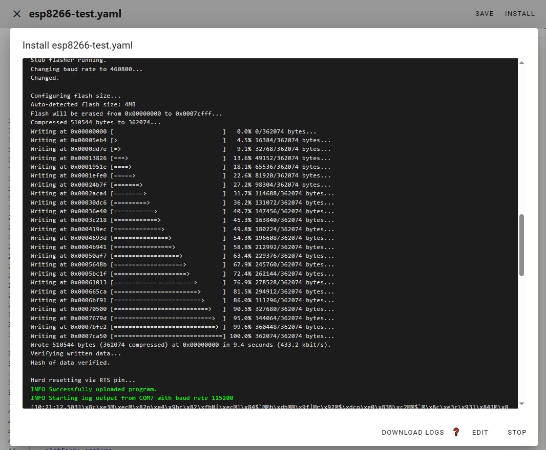
Save, connect your device to a USB port on your computer, click Install, select “Plug into the computer running ESPHome Device Builder,” and choose the correct serial port for your device. Wait while the firmware compiles and flashes to your device. If successful, you should see this:
-
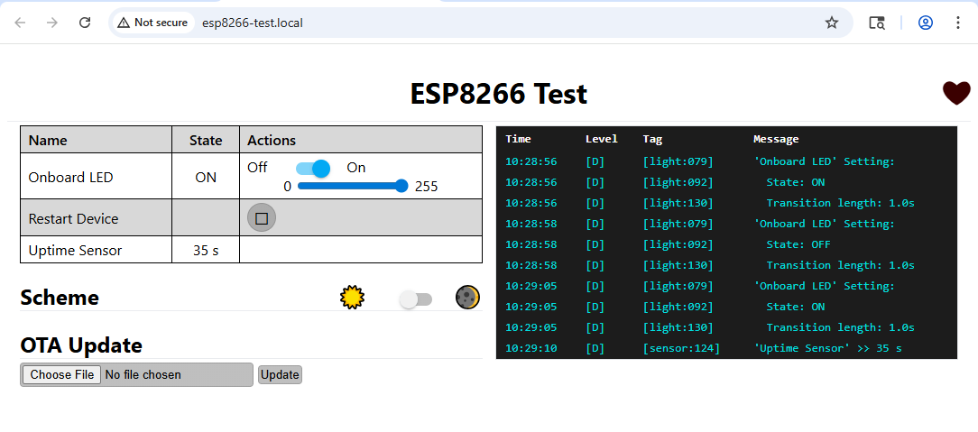
Click “Stop” to disconnect from the device, then click Visit to open the device's web interface. There, you can control the onboard LED, restart the device, and watch the Uptime sensor update every 30 seconds.
-
The last step is to connect it to the HS ESPHome plugin as explained in the Setup section