Use this guide when wiring the WS300 in a single pole (1-switch) or 3-way (multi-switch) circuit.
Circuit Types
Single Pole Circuit
A single pole circuit is designed to control a light or device from one location. This is the most common circuit type in most homes. The wiring diagram below illustrations how to install the WS300 in this type of circuit.
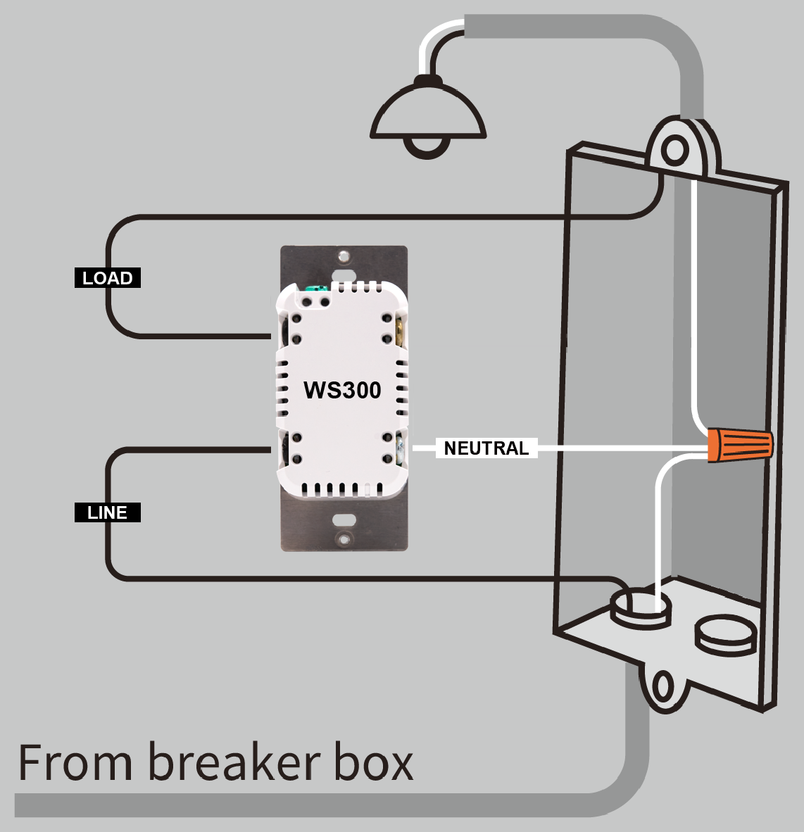
If present, the ground wire (not pictured) should be connected to the green terminal on the top of the WS300.
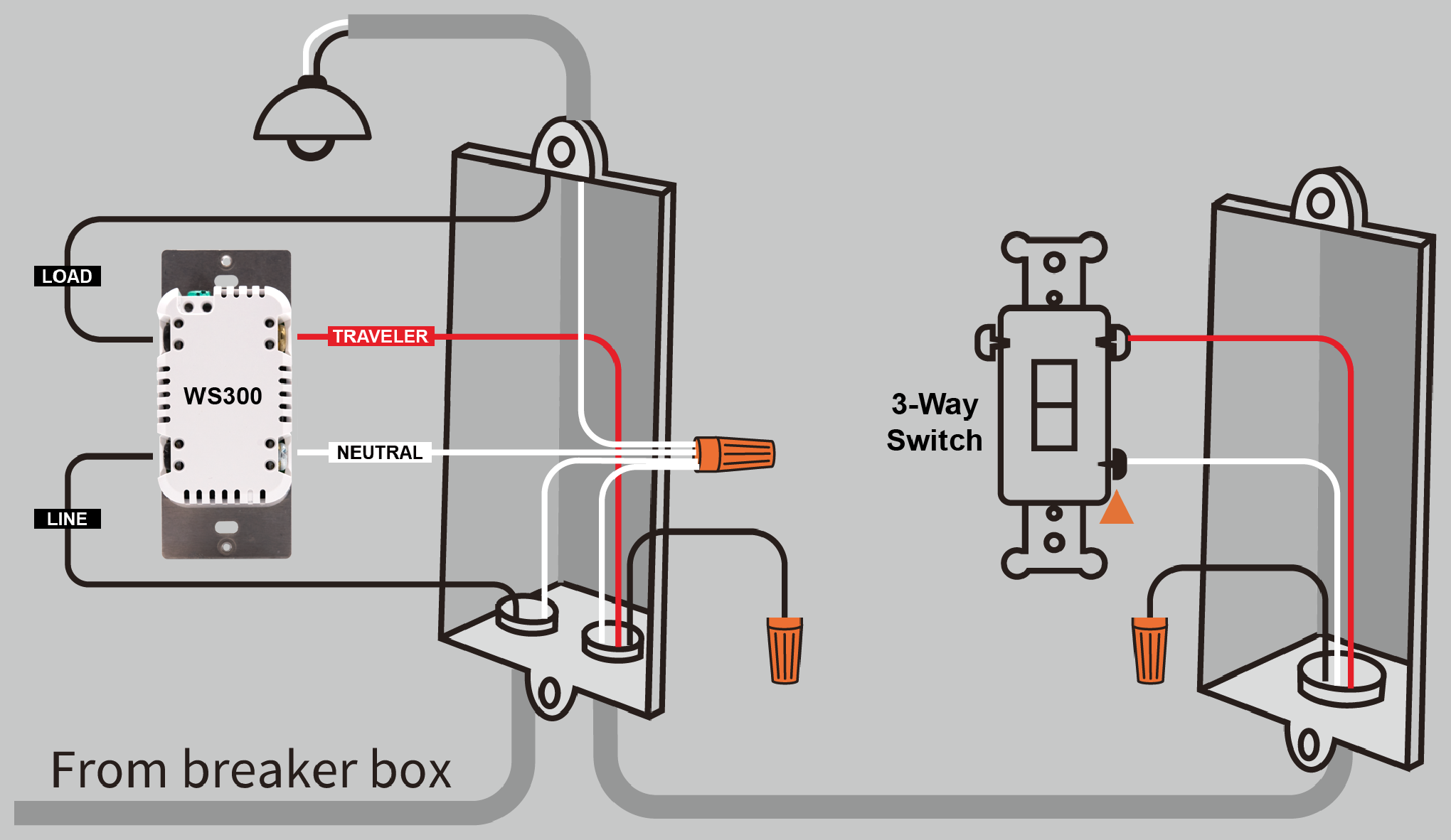
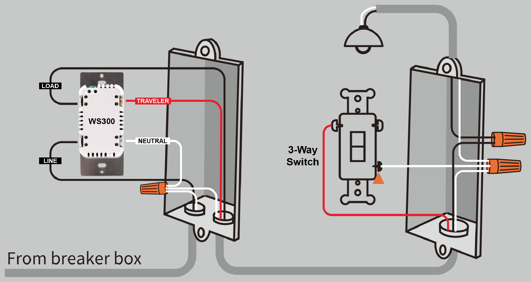
3-Way Circuit
A 3-way circuit allows a light or device to be controlled from two different locations, which is common in places like stairways, hallways, or large rooms.
There are several ways to wire a 3-way circuit, but the diagrams below show two common configurations. In Figure B, the load wire is located in the same (local) electrical box as the WS300. In Figure C, the load wire is located in the other (remote) box with the standard 3-way switch.
Any standard wall switch may be used as the accessory switch. You can also use companion switches such as the compatible Jasco models by setting Z-Wave parameter 40 to 1 (pulse mode). See WS300 Features, Specs & Warranty for more information about setting Z-Wave parameters.
If a traveler wire is not available, or if you want multi-tap scene control at both switch locations, you may install another HomeSeer WS300 Smart Wall Switch in the second box, provided that a neutral wire is present.
|
|
If present, the ground wire (not pictured) should be connected to the green terminal on the top of the WS300.
CAUTION: If your wiring differs from these configurations, you may need to use a multi-meter to identify the wires and determine the correct wiring configuration.
Before You Begin
WARNING: Risk of fire, electrical shock, or burns. Do not use this switch to control devices that could create a hazard if operated remotely or unattended. Do not use with medical or life-support equipment.
CAUTION: To prevent overheating or equipment damage, do not exceed the maximum rated load.
IMPORTANT: Verify that power is off before touching any wiring. If you are unsure about wiring, consult a licensed electrician.
Requirements
-
Neutral wire required
-
120V AC lighting circuit
-
Compatible Z-Wave controller or hub
-
Single-pole or 3-way switch wiring
Tools Needed
-
Flathead screwdriver
-
Phillips screwdriver
-
Wire cutter / stripper
Safety Warning
Turn OFF power at the circuit breaker before installing the switch.
Verify that power is off before touching any wiring.
If you are unsure about wiring, consult a licensed electrician.
Wiring Overview
The WS300 requires the following connections:
|
Terminal |
Typical Wire Color |
Function |
|---|---|---|
|
LINE |
Black |
Incoming power |
|
LOAD |
Black |
Power to light/device |
|
NEUTRAL |
White |
Neutral wire |
|
GROUND |
Green or bare |
Ground connection |
|
TRAVELER |
Red or other |
Used in 3-way circuits |
Wire colors may vary. Use a multi-meter if necessary to confirm connections.
Installation Steps
Use the information above to determine the correct wiring configuration. Then follow the steps below.
-
Turn off power at the circuit breaker.
-
Remove the existing wall plate and mounting screws.
-
Pull the existing switch out of the electrical box.
-
Identify and label the existing wires.
-
Disconnect the wires from the old switch.
-
Strip about 5/8 in (16 mm) of insulation from each wire.
-
Insert each wire into the appropriate WS300 screw terminal and tighten securely.
-
Carefully place the switch back into the electrical box.
-
Attach the wall plate.
-
Restore power at the breaker.